

LED Backhaul Project Engineer Blog
Use your own 3D printer: Fused Deposition Modeling
Last Update: Aug 10th, 2021
Introduction
We have a 3D printer with Fused Deposition Modeling (FDM / FFF), and we manufacture jigs for verification, parts for experiments, and small items to make the office a little more comfortable. The 3D printer I own is De AGOSTINI's idbox, and I'm using the one that was originally owned by other employees. (Because each part is exhausted due to long-term operation, we are considering updating)
3D printers are used for additive manufacturing (AM), which is the opposite of the removal process, in which the base material is cut and formed layer by layer according to the shape of the object. Unlike the removal process, shavings (chips) are not generated during modeling, and there is no need to drive a large motor that causes noise, so it is easy to place a small desktop device in the office and operate it.
This time, using such a small 3D printer, we will actually manufacture small items that make the office a little more convenient.
3D Printer FDM
The FDM 3D printer, which melts thin rod-shaped filament with a heater and forms objects by squeezing them with a nozzle to build them up one layer at a time, is probably the closest to the image of a 3D printer that the general public has. Since the material filament is solid, it is very easy to handle for storage and replacement, and since it is melted and formed by heat, it is possible to handle various materials such as PLA, ABS, TPU, and filler added to adjust the texture and strength. On the other hand, since it has moving parts in the three axes of XYZ, the accuracy is relatively poor, and the surface of the formed object will have laminate marks that show that it was made with a 3D printer, so post-processing is necessary if you want a beautiful surface. Also, since the bonding strength of each layer is low and the strength of the object is anisotropic, care must be taken in the direction of the object when creating parts that require strength.
Actual modeling
The cover of the air conditioner's control panel was partially damaged, making it difficult to open and close the cover, so I decided to make a part to repair the cover. The part where you put your fingers to open the cover is missing, so we will try to make a part to recreate and enlarge the part where you put your fingers.
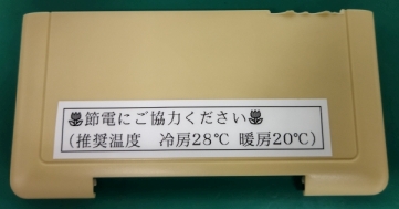
Figure 1: Damaged cover
Measure the area to be attached to the cover with double-sided tape. Be sure to take the measurements, as they will be used as the foundation for the design of the model. Based on the measured values, design the parts using 3D CAD software. Using the measurements taken earlier as a reference, the base is 25x20mm, t=2, and the part for fingers is a trapezoidal shape with a height of 10mm, slightly exaggerated. Once the design of the parts is complete, export the 3D model surface as an "STL file", which is a layered representation of microscopic triangles.
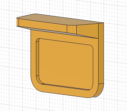
Figure 2: Design of parts
The STL file is then imported into the slicing software and converted into "G-code", which slices the 3D model layer by layer into thin slices and contains information such as the path and speed of the nozzle movement and the temperature of the nozzle. In this way, the 3D model can be sliced layer by layer.
note: It is not easy to adjust the various parameters when converting the G-code, because it requires craftsmanship and adjustment based on experience and intuition from test-printed models.
After importing the G-code file into the 3D printer driver software and pressing the start button, wait until the molding process is completed. Be sure to check the nozzle and filament periodically to make sure they are working properly, as the 3D printer may fail during the molding process.
After several tens of minutes of molding time, the finished part is shown here. There is no need to do any surface treatment, so we stuck it to the cover with double-sided tape.
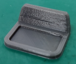
Figure 3: Molded parts
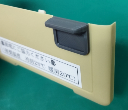
Figure 4: Attaching the cover
This is a cover that has been returned to its original position, and the area to put your fingers on has been enlarged so that it can be easily opened and closed.
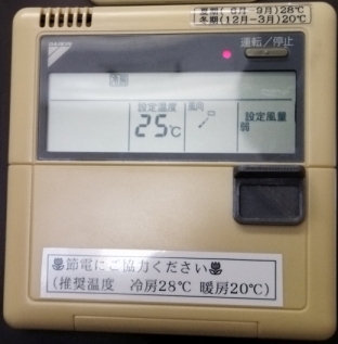
Figure 5: The revived cover
Realization and utilization of ideas
As you can see, it is a revolutionary machine in the sense that it allows us to easily give shape to things that we feel are inconvenient but are still used as they are, or ideas that we wish we had, with tabletop-level equipment.
In one of our experiments, we made a stopper to prevent the power connector of our LED Backhaul main board from being disconnected. The LED Backhaul product version uses a sheet metal connector retaining part, but the retaining part interferes with the lens to reduce the distance between the lens and the board, so we experimented with a self-made part made by a 3D printer.
In one case, we made a prototype of a component that would form the basis of a compact measuring instrument in a short period of time, incorporating the opinions of engineers in the field, and used it to make a proposal to a customer.
If you are looking for accuracy and aesthetics, an outsourced 3D printing service may be more suitable, but for rapid prototyping, it is still convenient to have your own equipment for repeated prototyping and improvement.